
1.Purpose
The secondary overvoltage protector for current transformers is primarily designed to safeguard against abnormal overvoltages on the secondary side of various CTs.The protector is securely connected across the secondary windings of the CT,exhibiting a high-impedance state with minimal leakage current during normal operation.In the event of an open circuit in the CT's secondary circuit or abnormal overcurrent in the primary winding,the overvoltage generated by the secondary winding prompts the protector to swiftly actuate,short-circuiting the secondary side of the CT.The fault location is automatically displayed on the panel,accompanied by a passive contact signal output.Once the fault is resolved,pressing the manual reset button(or allowing the CTB to automatically reset)restores the circuit to its original state,enabling it to resume normal operation.
II.Basic functions
1.The input impedance is greater than 100MΩ,and it does not affect any measurement and protection performance after being connected;
2.The secondary side protection voltage can be set by oneself to meet the needs of different occasions;
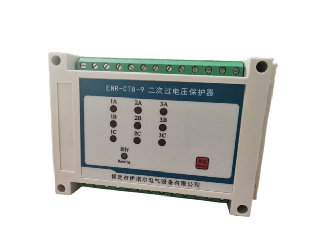
3.After protection,the location of the fault point is displayed,facilitating fault removal;
4.After protection,there is a contact signal output,which facilitates system connection and use;
5.Post-protection resetting offers two options:manual button resetting and automatic resetting upon fault clearance,allowing users to choose as per their preference;
6.Adopting a design that conserves space and utilizes track installation,making it convenient for installation and use.
III.On-site inspection
3.1 The protector should be tested before use.When using a multimeter in the resistance range to test between terminals A(or B or C)and N,the insulation resistance value should be greater than several megohms.
3.2 During the action value test,first adjust the voltage regulator to the 0V position,connect the protector and the voltage regulator to AC220V power supply,and the protector's working indicator light will be on.Slowly increase the output voltage of the voltage regulator to the action voltage value of the protector,and instantly apply this voltage across the A(or B or C)and N terminals of the protector.At this point,the protector should actuate,and the corresponding action indicator light will be on.At the same time,use a multimeter to measure the output contacts of the protector.The open contacts should close,and finally,press the reset button.After the protector resets,the action indicator light should be off.
A current-limiting resistor should be added to the test circuit to adjust the output current within the range of 0.1A to 5A.